Step 3 · Electrical Interconnection
Step 3 is the electrical core of the Design Tool. You build and validate the one-line graph, complete every device's attributes, confirm grounding and bonding, and resolve the grid tie-in — so the design passes NEC 705 and can feed conductor sizing in Step 4.
It is the most interaction-heavy step. The three things worth learning first are: how the graph is authored (the halo + drag-to-wire), how to drive it to "done" (Required fields → Next missing), and how to read the compliance band. Everything else is per-device data entry.
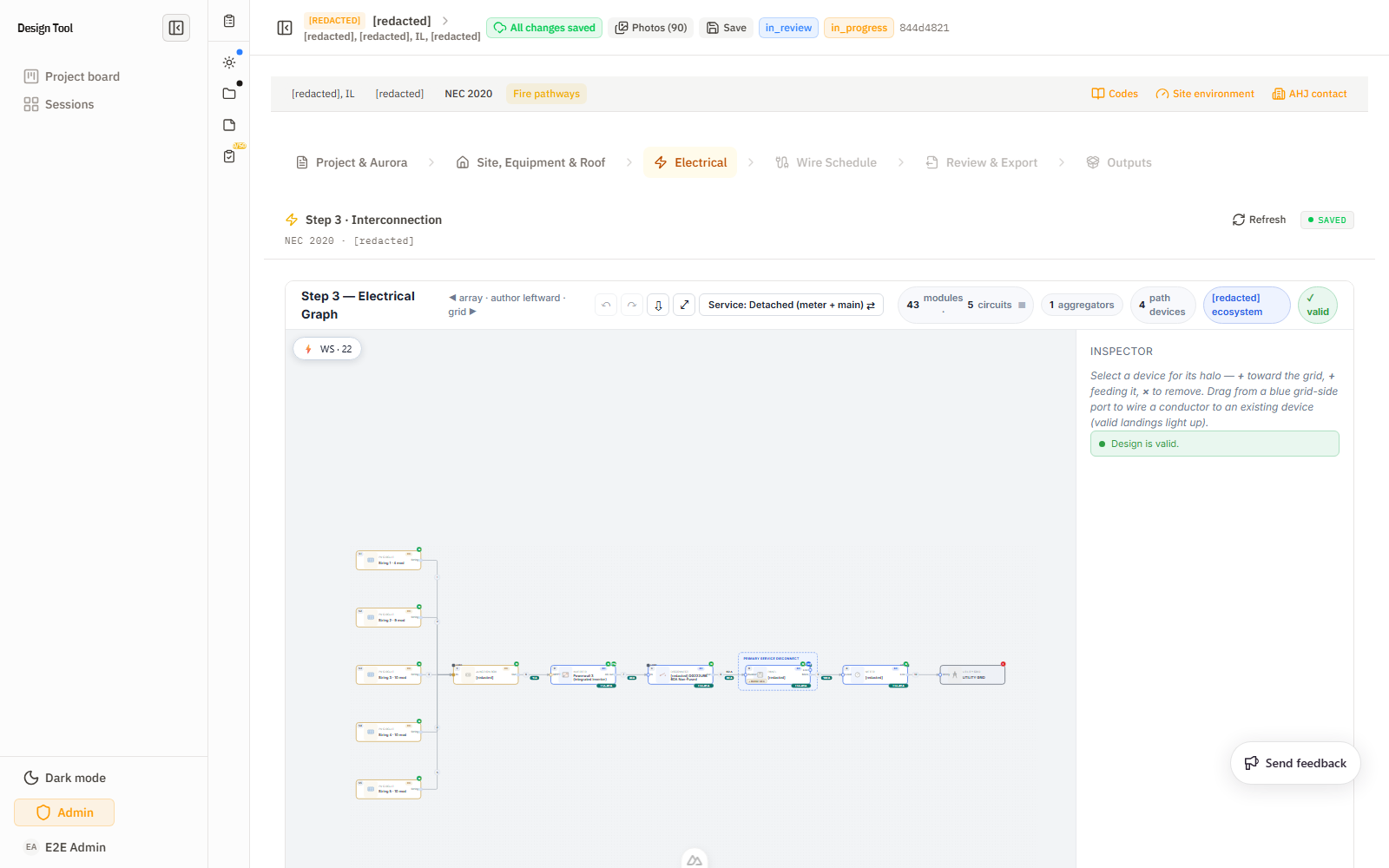
Reading the one-line graph
The canvas is an interactive SVG one-line. It is laid out array on the left, grid on the right — the toolbar hint reads ◀ array · author leftward · grid ▶. Conductors flow array → PV circuit → junction box → combiner/inverter → battery → disconnect → panel (MSP) → meter → utility grid.
- Device labels (A, B, C…) tag each path device top-to-bottom; the inspector cards below the canvas use the same letters, so "Device B" on the card is the "B" node on the graph.
- Wire numbers + amperage callouts on each edge (e.g.
16 A,45 A,PV 80 A,ESS 30 A) are the live current the graph is carrying — a fast sanity check that ratings make sense before Step 4 sizes them. - The stats bar summarizes the graph: e.g.
25 modules · 3 circuits · 1 aggregator · 4 path devices · Tesla ecosystem · ✓ valid. The✓ validflag (vs an error count) is the headline "is the topology legal?" indicator. - Service topology toggle (
Service: Detached (meter + main) ⇄) switches between a detached meter-main (separate meter and main, common in CA) and an attached meter-main. Get this right early — it changes which grounding/bonding fields apply and where the service disconnect lives. - Live Wire-Schedule preview (
⚡ WS · N) expands the raceways Step 3 is producing right now — an early check that your edits are generating the segments you expect, before you reach Step 4.
Authoring with the halo (the core interaction)
You don't draw boxes — you select a device and use its halo. Click any node and the Inspector shows the halo controls:
+toward grid — add the next device on the grid (service) side of the selected one.+feeding it — add a device on the array (source) side.×— remove the selected device.- Drag-to-wire — drag from the blue grid-side port to connect two existing nodes.
The most common authoring mistake: trying to add a service-region device (gateway, backup switch, meter collar) from the inverter or combiner. Those sit on the array-production side, which is not eligible for service equipment — you'll see "No eligible devices here." Service-region devices must be added from the utility meter or the MSP, toward the service side. (See Troubleshooting → "No Eligible Devices Here".)
Driving to "done": Required fields → Next missing
The fastest path through Step 3 is not reading every card — it's the completion loop at the top of the inspector:
- Switch between the Equipment and Edges & Raceways tabs — required data lives on both (device attributes vs. conductor/raceway details).
- The banner shows
Required fields · N missing;Next missing →jumps you straight to the next blocking field. Hide completecollapses everything you've already finished so only the gaps remain.
Items marked RECOMMENDED (e.g. "Auto on the electrical one-line is not yet confirmed") are advisory — they won't block the step, but resolving them removes ambiguity for the reviewer. Hard-required items will block Next until cleared. (See Troubleshooting → "Required Fields Missing" and "Step Won't Advance".)
Service Grounding & Bonding
This section gates the service connection. It has three controls, each tied to an NEC article shown inline:
- Listed as service equipment (SUSE)? — Yes/No toggle. Declares whether the panel/disconnect is rated as Suitable for Use as Service Equipment.
- Main bonding jumper (250.24(B)) — a Confirm button. The N-G bond happens once, at the service disconnecting means; confirming records where.
- Grounding electrode (GEC) (250.24(D)) — a dropdown, with a "Suggested: reuse existing" shortcut for retrofits where the existing grounding electrode system is reused.
A ⚠ N needed badge on the section header means one of these still blocks completion.
Per-device cards (A–D…)
Each path device has a collapsible inspector card. The fields that matter most downstream:
- Utility Meter — meter style / class / form code, Existing/New, service feed (Overhead/Underground), new riser/wire flags, available fault current.
- Main Service Panel (MSP) — Existing/New, bus rating, main breaker (+ New/Existing), secondary main rating, and the Interconnection Survey sub-section (Room for PV breaker, Existing solar/battery breakers on bus, Space for tap). These three feed the 705.12 busbar math directly.
- Disconnect — Disconnect Role (PV / ESS / etc.) and location.
- Inverter / Combiner / Powerwall — aggregate PV breaker rating, pcsControlMode, and Power Control (PCS) mode.
Set New vs Existing honestly on every device — it drives both the BOM and which conductors/breakers the wire schedule treats as already in place.
Tie-Ins — where the system lands and why it qualifies
Most user confusion happens around the tie-in card. The card explains where the DER system lands and why it's legal. Which card you see depends on how the system connects to the service:
- Backfed breaker (load-side, NEC 705.12): the system lands on a breaker in the MSP, and that breaker is the interconnection OCPD. The 120% busbar rule (705.12(B)(3)) applies; the tool checks the bus rating against the main + the back-fed PV breaker.
- Load-side tap (705.12(B) taps): the system taps a feeder rather than a breaker; the tap/disconnect OCPD must be represented correctly. The export refuses if the landing has no breaker rating to size the tap against (see Troubleshooting → "Load-Side Tap Has No Breaker Rating").
- Supply-side / line-side (705.11): the system connects ahead of the main service disconnect, per 705.11 and 230.82(6). Service-side rules and disconnect placement matter — the source needs its own service-rated disconnecting means.
- PCS active (705.13): a power control system can qualify an otherwise-constrained busbar by limiting export; set it when a back-fed breaker would otherwise bust the 120% rule. (NEC 2023 reclassifies PCS as a sub-type of EMS — the tool tracks the project's adopted edition.)
A declared tie-in card shows its status (Connected), its route (e.g. 011 MS25 · Breaker Tie-In · Backfed breaker), the PV backfeed current, the live compliance check, and Saved / Remove controls. ▸ Show all landing options reveals alternate landing devices if the default isn't what you want.
Reading the compliance band
The compliance verdict is live and per tie-in — it grades each declared source against the bus it lands on, and updates as you edit. Two things to understand:
- It needs a declared tie-in to grade. The panel reads "Set the panel bus rating, main breaker, and PV breaker to evaluate" until those exist. An undeclared back-fed breaker reads "incomplete," never a false PASS — so an empty verdict means "not enough data," not "compliant."
- A failing 705.12(B)(3) check spells out the math. Example from a real 200 A panel with a 60 A PV backfeed:
Bus over by 20 A · 200 A × 120% = 240 A < 200 A main + 60 A PV = 260 A
i.e. the allowed busbar load (240 A) is less than main + backfeed (260 A), over by 20 A. The card offers a remediation suggestion — typically a smaller backfed breaker, a higher-rated bus, a supply-side move, or PCS active to waive the limit.
When the gateway IS the service disconnect (whole-home / Tesla Gateway 3)
A Tesla Gateway 3 (and similar grid-forming devices) placed upstream of the main service panel does not land on a load-side breaker — it becomes the service disconnect and point of interconnection itself (a supply-side 705.11 connection per 230.82(6)). For these designs:
- There is no separate load-side tie-in card to fill in. The interconnection is the service connection; the tool derives it from the one-line (the gateway shows as the service disconnecting means).
- You establish it by crowning the gateway after you place it: choose "Make service disconnect" (keep the existing panel inline) or "Back up the existing MSP" (re-home the existing panel behind the gateway), then pick the NEC-sized main breaker the tool recommends and confirm service bonding/grounding.
- An empty "Grid Tie-Ins" list is expected here — it is not a missing field.
Adding an islanding or backup device (Gateway 3, Backup Switch, IQ Meter Collar)
Islanding / microgrid-interconnect devices are service-region equipment. Open the halo on the utility meter or the MSP and add the device toward the service side — not from the inverter/combiner (which lives on the array side and shows "No eligible devices here"). See the halo section above.
What To Check Before Continuing
- The graph topology matches the intended array-to-grid path, and the stats bar shows
✓ valid. - Required devices are present: service point, meter, MSP, inverter/combiner, disconnects, batteries, junction boxes, PV circuits.
- Service topology (detached vs attached meter-main) is correct.
- Every device has correct New/Existing, ratings, catalog/SKU, OCPD, and location data.
- Grounding & bonding (SUSE, MBJ, GEC) is complete — no
⚠ neededbadge. - The tie-in has the correct landing device, method, side, breaker/tap, and termination confirmation — and the compliance band reads PASS (or the empty-list case is the expected whole-home one).
Required fields · 0 missingbefore you click Next.
Feeds Next
Step 4 (Wire Schedule) consumes the validated graph, device ratings, path devices, tie-in data, and compliance state to auto-generate conductor sizing and the raceway table. If Step 3 is incomplete or invalid, the wire schedule will be incomplete, blocked, or misleading.
Short Clips
A short walkthrough of the Step 3 electrical graph: