Step 4 · Wire Schedule
Step 4 reviews the conductor schedule the tool derives from your completed design — you don't author it, you verify it. It turns the Step 3 graph into raceways with conductor quantities, wire sizes, ampacity calculations, temperature deratings, EGC sizing, OCPD values, and voltage-drop results.
The page looks dense, but it answers one question per row: "is this conductor big enough for the current it carries, after every NEC derate?" Learn to read one row and you can read the whole table.
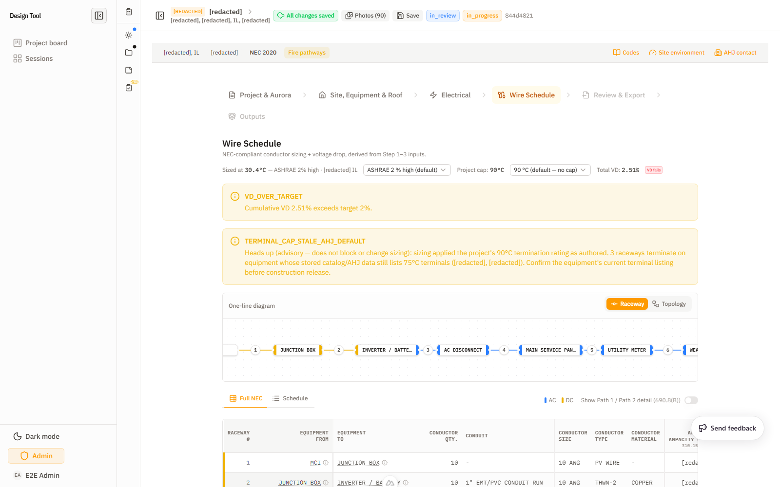
The header: what the whole table is sized against
Before reading rows, check the three header controls — they apply to every raceway:
- Ambient temperature + method — e.g.
30.4 °C — ASHRAE 2% high · City of Irvine CA, with a Temperature Method selector (ASHRAE 2% high is the default). This is the ambient the temperature-correction column derates from. Wrong ambient → wrong ampacity everywhere. - Project Cap — e.g.
90 °C (default — no cap). Caps the terminal/insulation column the table sizes to. Some AHJs force a 75 °C cap; if so, set it here. - Total VD readout — e.g.
1.50% — VD passes. The whole-system voltage drop. It flips to a warning badge when the run exceeds target.
Reading one raceway row (the derate chain)
The Full NEC table shows every step of the NEC ampacity math as its own column, left to right. For any row, the chain is:
- Starting Allowable Ampacity @ 90 °C — the conductor's base ampacity from its insulation column (690.8(B) / Table 310.16).
- × Temperature Correction — derate for the ambient above 30 °C (the header temp).
- × Adjustment Factor — derate for bundling / conduit fill (more current-carrying conductors in a raceway → lower factor).
- = Adjusted Ampacity — what the conductor can actually carry in this install condition.
- Terminal Ampacity — a separate limit: the lug/breaker termination rating at 110.14(C) (often the 75 °C column). The conductor must satisfy both the adjusted ampacity and the terminal limit.
- Required Ampacity — the load the run must serve (690.8(A) continuous current × 1.25, etc.).
The row passes when Adjusted Ampacity and Terminal Ampacity both ≥ Required Ampacity. The EGC columns (size/type/material) size the equipment grounding conductor per 250.122 off the OCPD; VD% is that segment's voltage-drop contribution.
Why two ampacity columns matter: a conductor can pass on its 90 °C insulation but still be limited by a 75 °C termination. The "Terminal Ampacity" column is where that 110.14(C) limit shows up — it's the most common reason a conductor is a size larger than the raw ampacity suggests.
Worked example — a load-side Enphase job (5 raceways)
A real AC-coupled Enphase design (10× IQ8HC micros + 1 IQ Battery + IQ Combiner, load-side backfed into a 200 A MSP) produces five segments:
| # | From → To | Conductor | VD% |
|---|---|---|---|
| 1 | Micro-inverter → Junction Box | 12 AWG Q-Cable | 0.33% |
| 2 | Junction Box → Combiner | 10 AWG THWN-2 | 0.53% |
| 3 | Battery → Combiner | 8 AWG THWN-2 | 0.48% |
| 4 | Combiner → AC Disconnect | 6 AWG THWN-2 | 0.99% |
| 5 | AC Disconnect → MSP / POI | 3 AWG THWN-2 | 1.50% |
The VD accumulates toward the POI — segment 5 carries the full system and lands at the 1.50% total. Conductor size steps up as current aggregates (12 → 10 → 6 → 3 AWG) moving toward the service. A whole-home Tesla job runs longer (e.g. 13 raceways) because the gateway, BLP, and protected/unprotected sides each add segments — same row-reading rules apply.
Views and controls
- Raceway / Topology diagram tabs — the one-line, either as numbered raceway segments or as the device topology.
- Full NEC / Schedule table tabs —
Full NECshows every derate column (above);Scheduleis the condensed permit view. They must agree on the intended output. - AC/DC toggle + 690.8(B) Path 1 / Path 2 detail switch — split the DC PV-circuit rows by the two 690.8(B) sizing paths.
- Clickable current / equipment cells — open a cell for review or an override.
- Segments (debug) row count — confirms the table row count matches the topology.
Warnings you may see
- Terminal cap stale (
TERMINAL_CAP_STALE_AHJ_DEFAULT): flags raceways whose terminal-temperature cap is still a stored AHJ/catalog default (e.g. a 75 °C default on an Eaton disconnect) rather than a confirmed value. Non-blocking advisory — review the flagged raceways and confirm or override so the 110.14(C) ampacity is sized against the right column. (See Troubleshooting → "Terminal Cap Stale".) - Voltage-drop over target: the total VD readout flips from "VD passes" to a warning badge. Review raceway lengths, conductor paths, current inputs, and OCPD before accepting or overriding. (See Troubleshooting → "Wire Schedule Voltage-Drop Warning".)
What To Check Before Continuing
- Raceway row count matches the Step 3 topology (use the Segments debug count).
- From/To columns follow the expected array-to-grid path.
- For each row, Adjusted and Terminal ampacity clear Required ampacity.
- Ambient temperature source and terminal cap are correct for the AHJ.
- Total VD passes (or an over-target warning is understood and resolved).
- Full NEC and Schedule views agree.
Feeds Next
The reviewed wire schedule feeds Step 5 (Review & Export). It becomes part of the permit package, construction-review packet, and downstream CAD/planset outputs — so an unreviewed warning here surfaces in the final deliverable.
Short Clip
A short walkthrough of the wire schedule: